Polaris
A three-node mesh communication system for search & rescue.
From human
stakes to data.
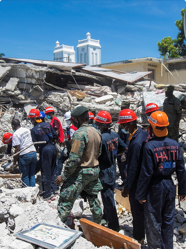
We started with a real person — not a statistic. Tsune's grandmother survived a disaster and waited to be found. That experience defined every design decision that followed.
.png)
"When the disaster hit, we had no way to tell anyone where we were. We could only wait and hope someone would find us."
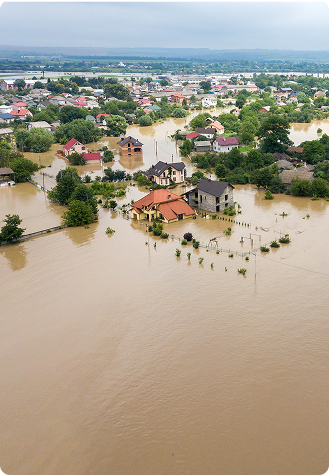
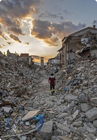
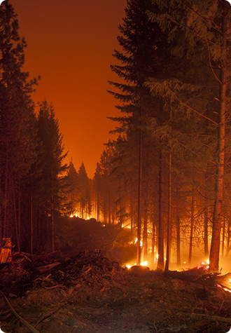
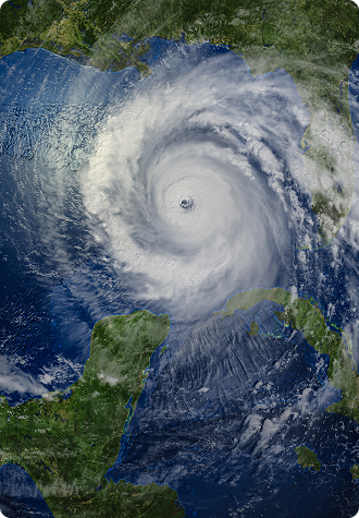
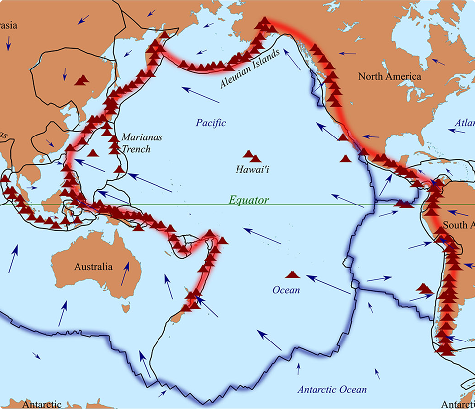
75% of the world's volcanoes and 90% of all earthquakes occur along the Ring of Fire — a zone where dense urban coastlines sit directly on fault lines. When those rupture, conventional infrastructure fails first and fastest.
Japan, New Zealand, the Pacific Coast of the Americas — all densely populated, all critically dependent on infrastructure that can collapse within seconds of a major seismic event.
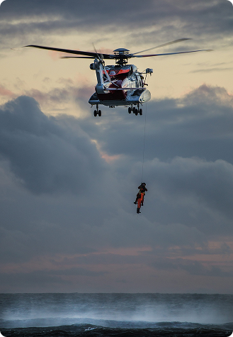
The SAR communication market is split between enterprise devices with subscription barriers and consumer GPS tools built for convenience, not disasters. Neither solves the core problem.

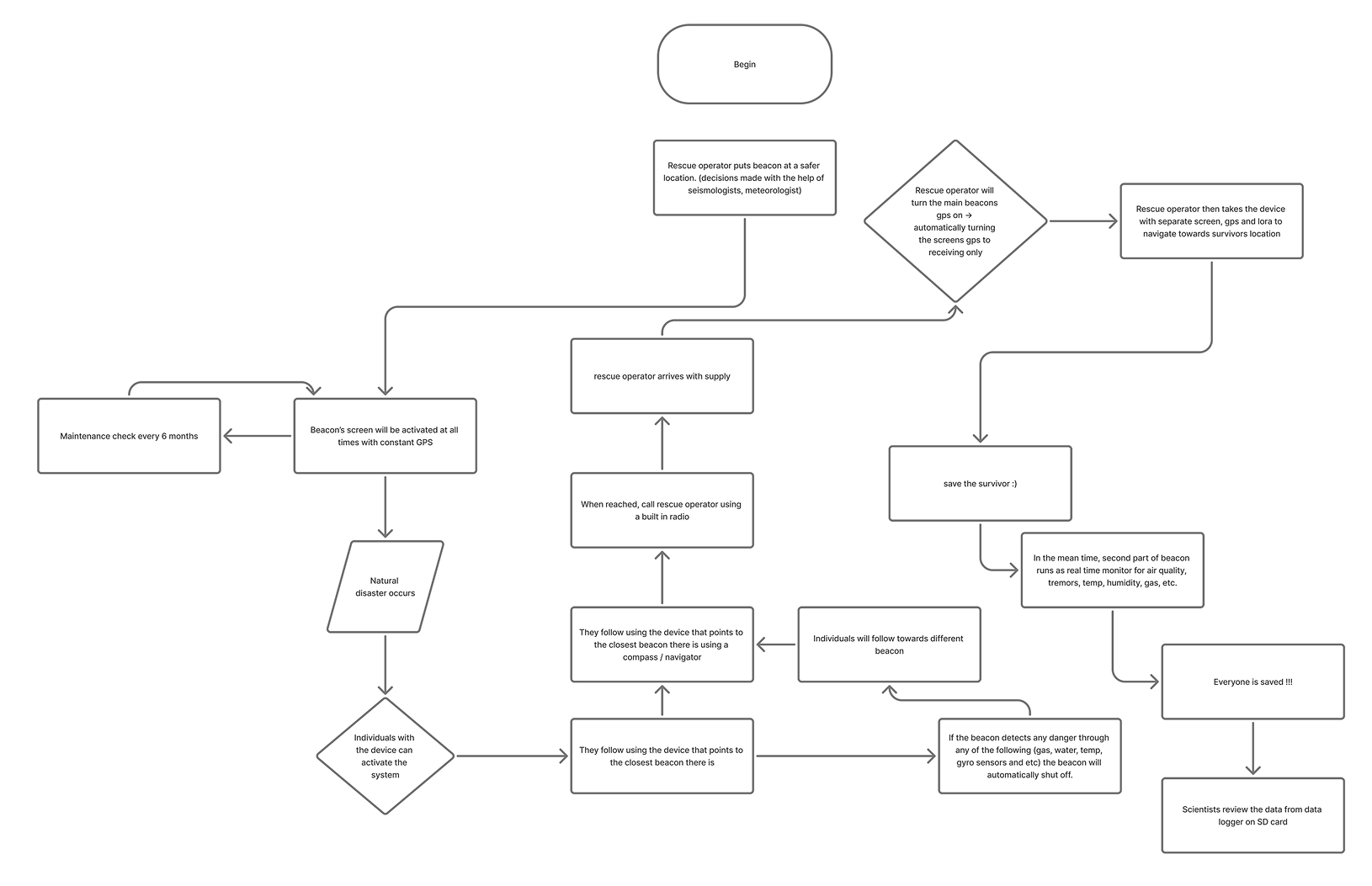
Two roles, one coordinated system. The SOS logic maps precisely across five phases — from the moment disaster strikes to confirmed rescue.
Shaping
the system.
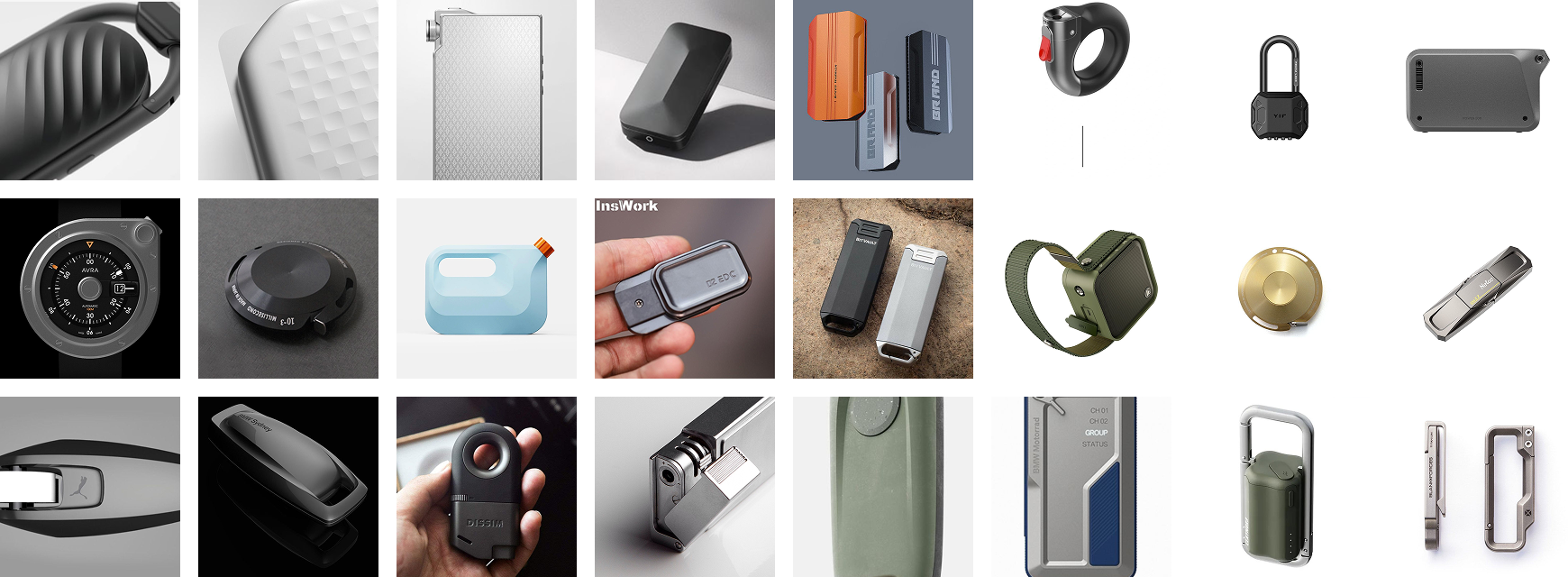
From moodboards and system architecture to initial sketches and form exploration — defining what Polaris should look like, feel like, and how all three nodes relate to each other.
The beacon needed to communicate permanence and authority — something you trust to run unattended at base camp for hours. We pulled from military field equipment, tripod-mounted hardware, and emergency broadcast devices. Matte surfaces, structural forms, purposeful weight.
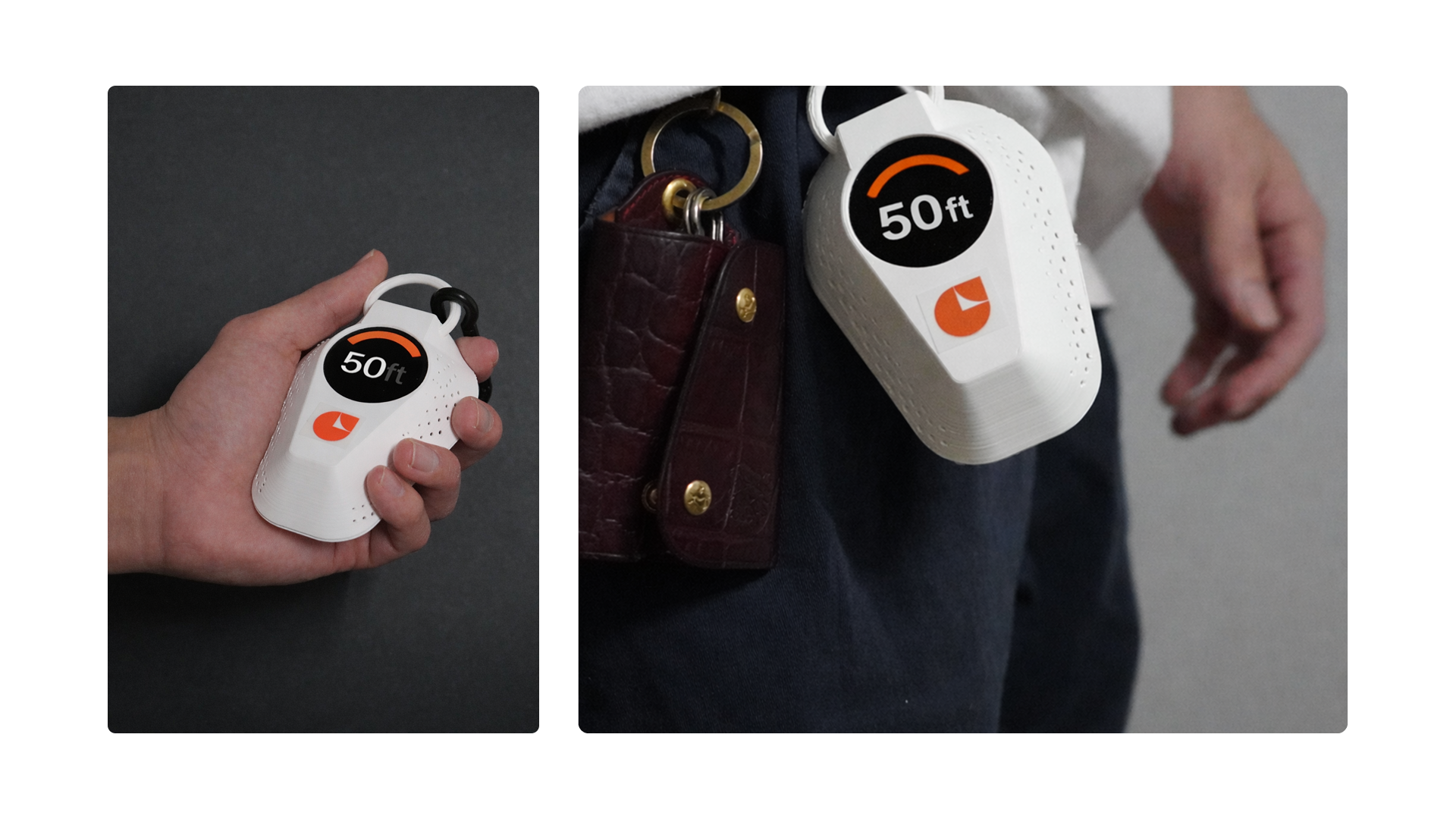
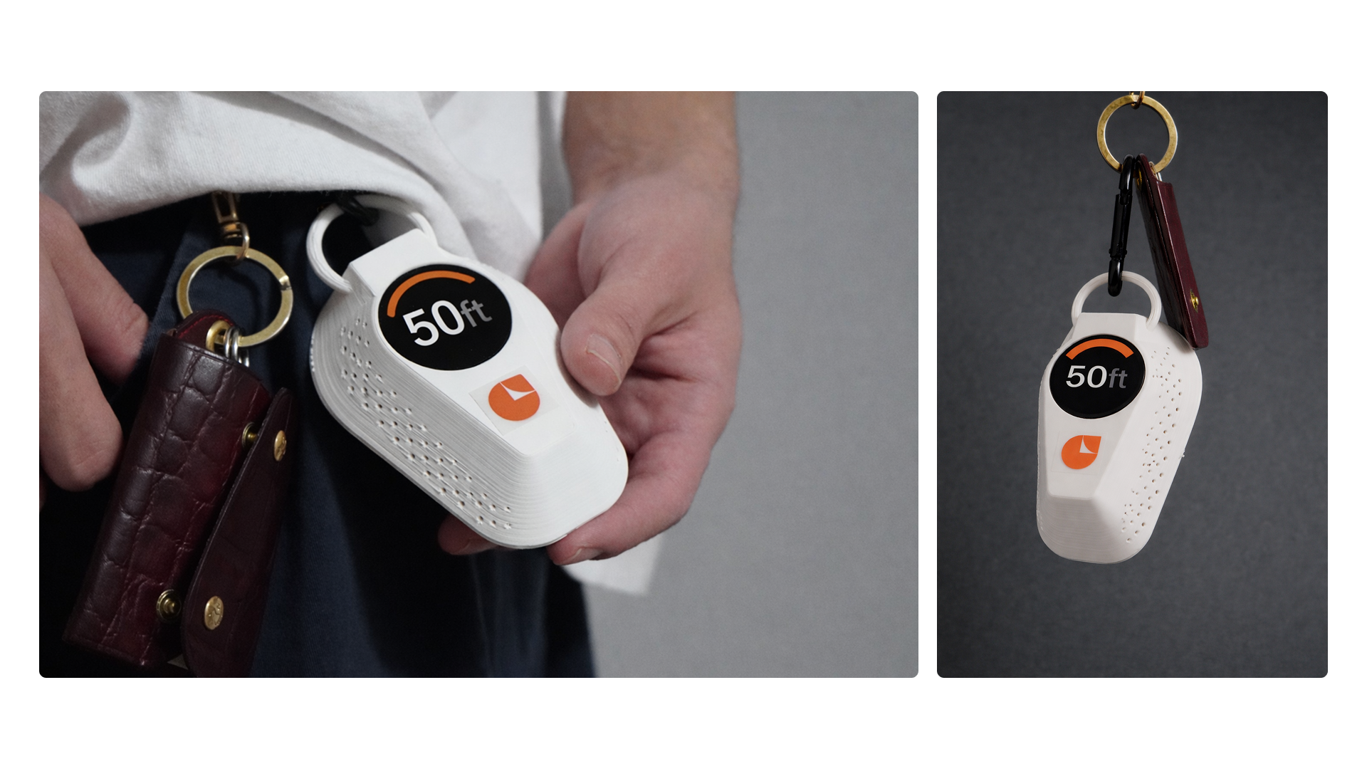
Node 3 needed to feel like something a survivor would carry — light, wearable, tactile under stress. Consumer-adjacent but hardened. We pulled from climbing gear, trail watches, and personal emergency kit.
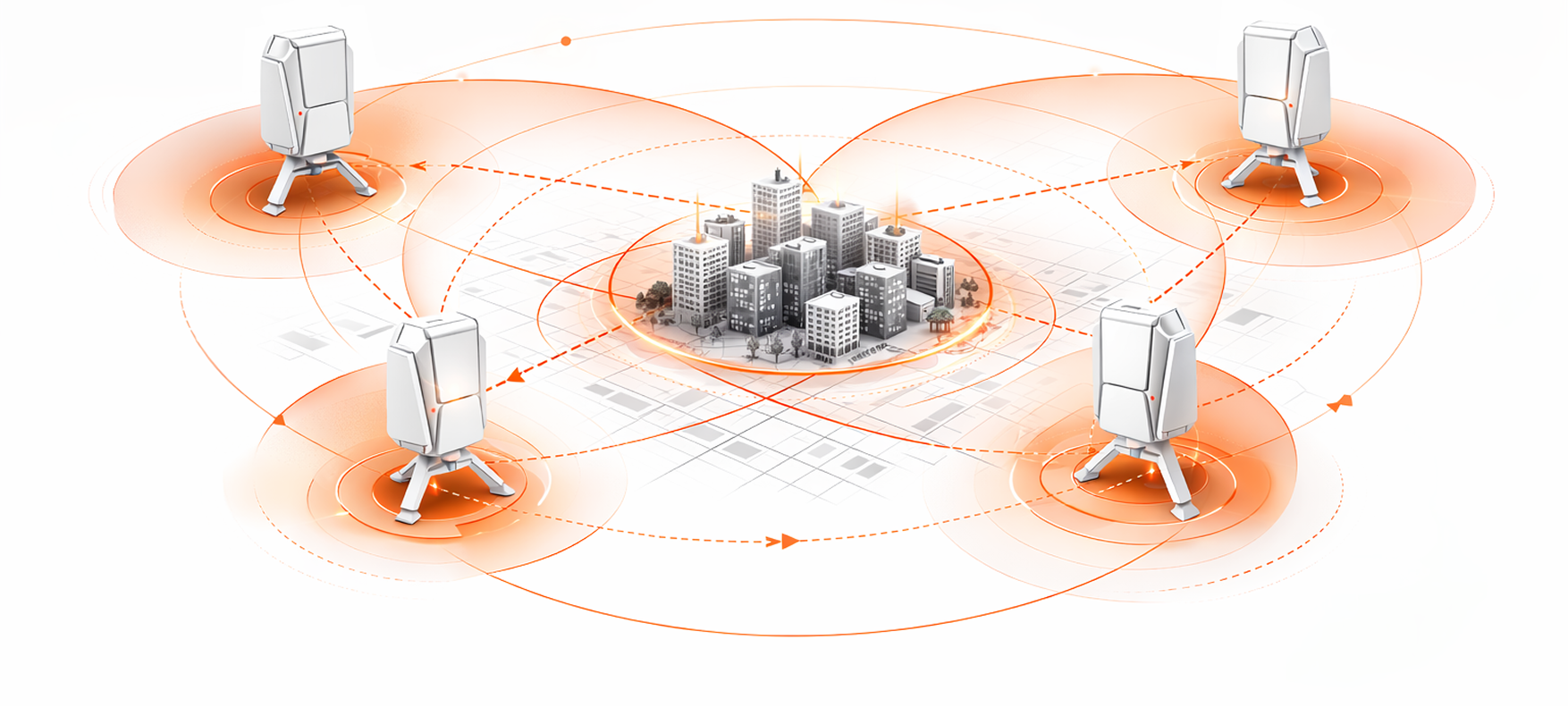
Each node doubles as a relay — every device deployed extends the network's reach. A single Node 1 at base plus two Node 2 relays covers several square kilometres with no single point of failure.
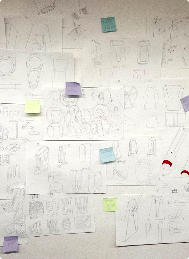
Early sketching explored the three nodes independently — how each needed to be held, worn, or mounted. Form followed function: we had to understand the use context before thinking about aesthetics.

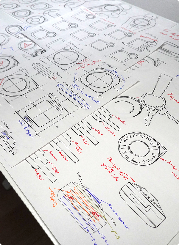
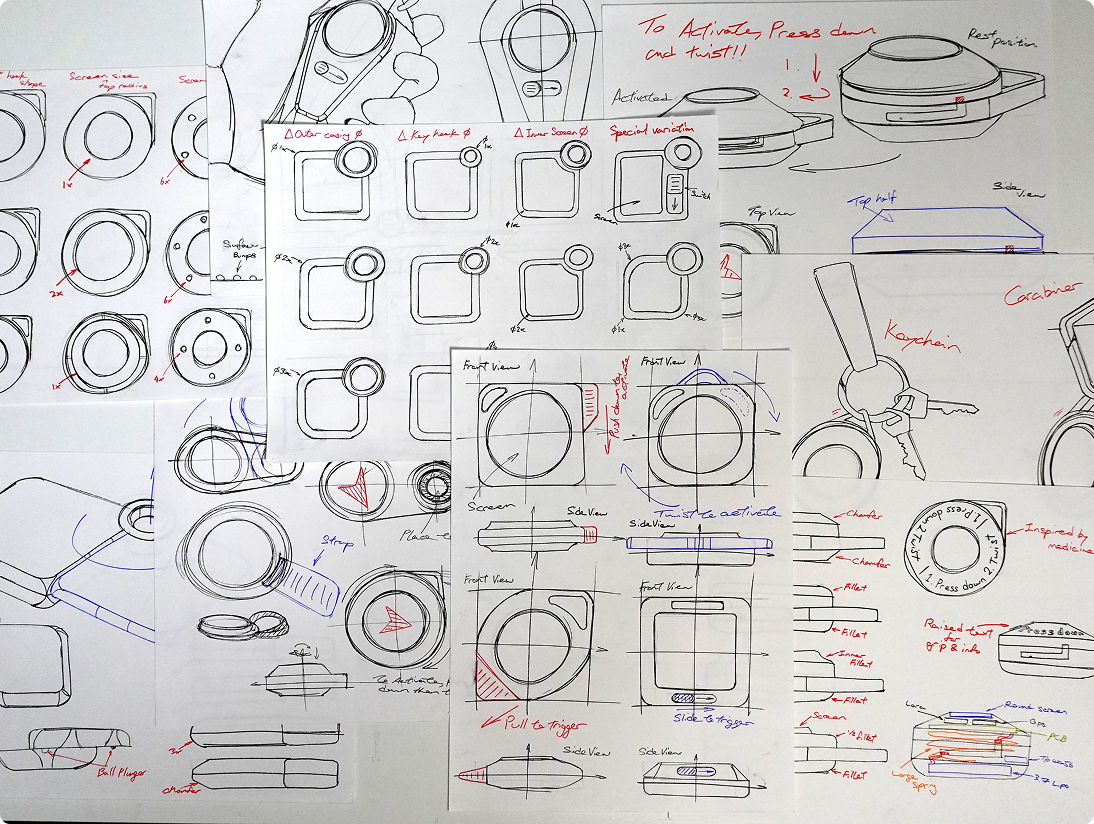
We explored wrist-mounted, leg-mounted, and clip-on form factors before settling on the compact handheld with belt clip for Node 3. Zero cognitive load to activate is the constraint that eliminated everything else.
Building
from scratch.
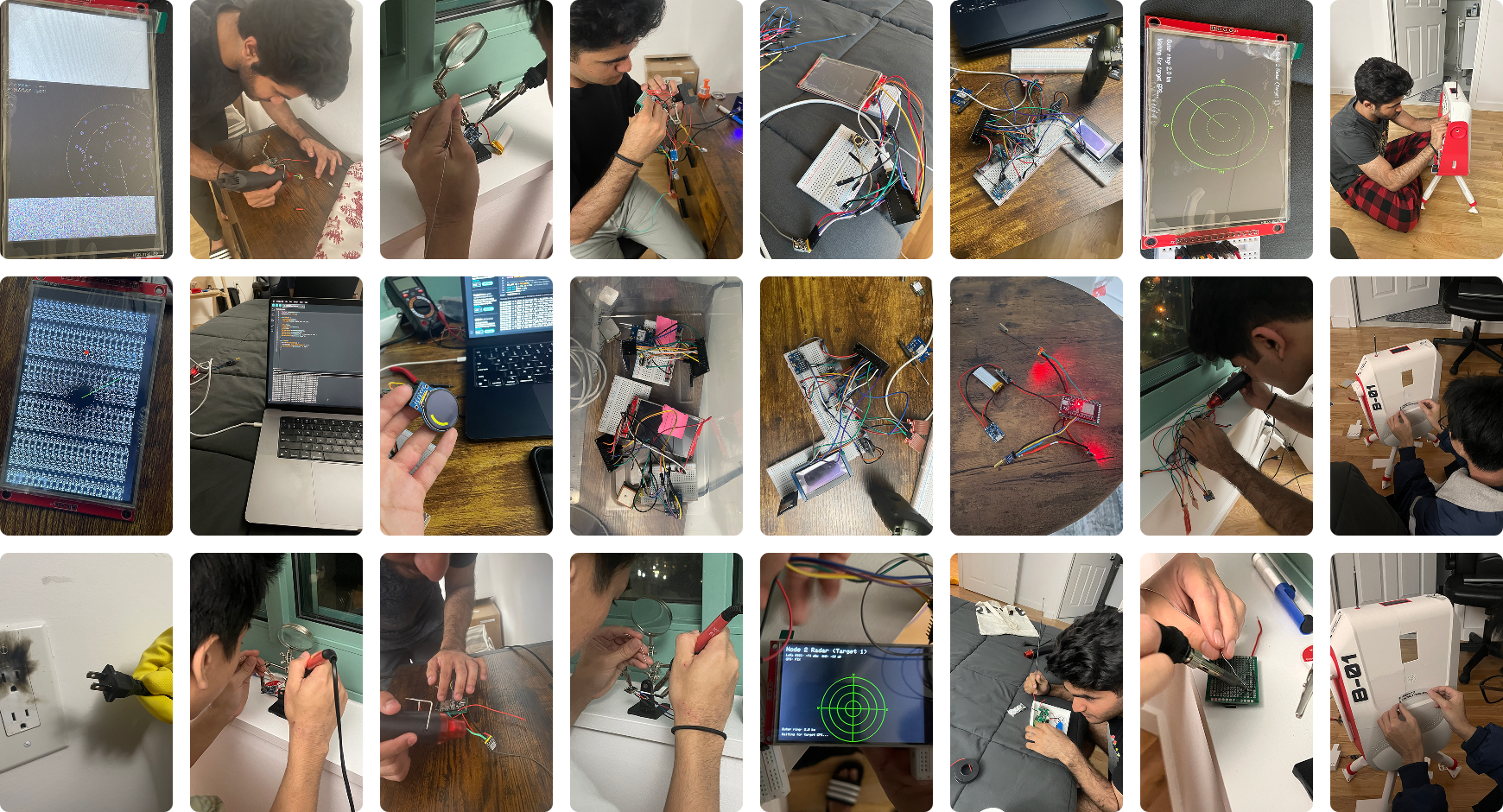
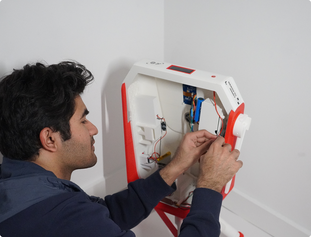
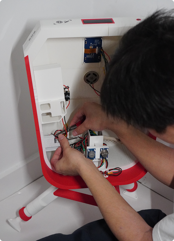
Every component sourced, every circuit wired, every line of firmware written. From hardware stack to final assembly — proving the system technically before designing it aesthetically.
Polaris is built entirely from off-the-shelf hardware. No custom silicon, no proprietary modules. Every component is sourceable for under $5, and every node is field-repairable with a soldering iron.
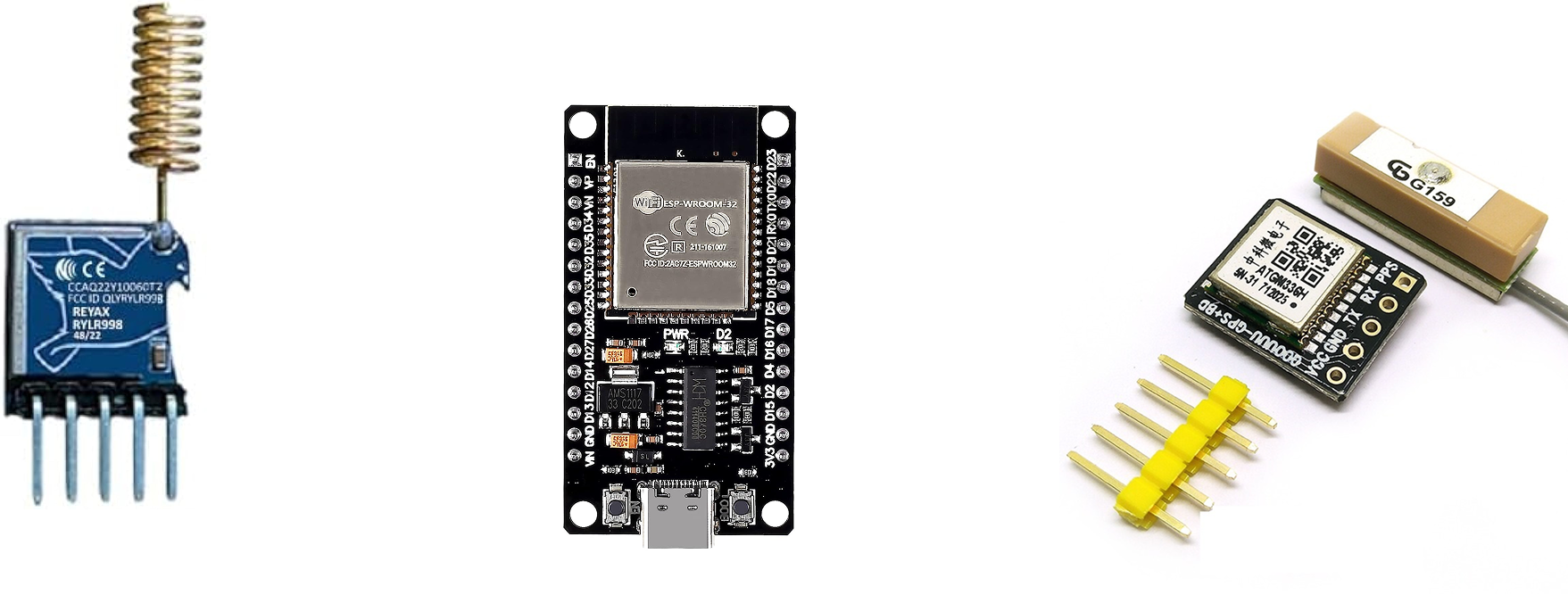
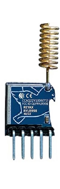
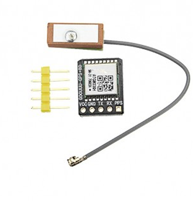
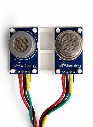
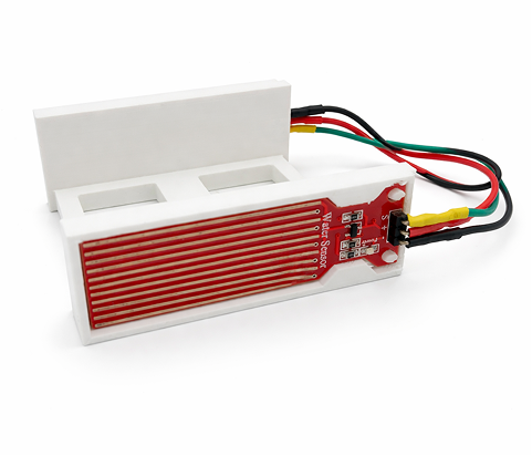
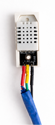
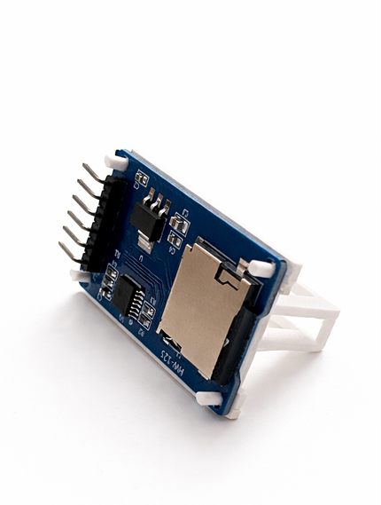
The RYLR998 LoRa transceiver and ATGM336H GPS module form the communication core of every node. The remaining sensors provide environmental situational awareness critical for rescue operators assessing ground conditions remotely.
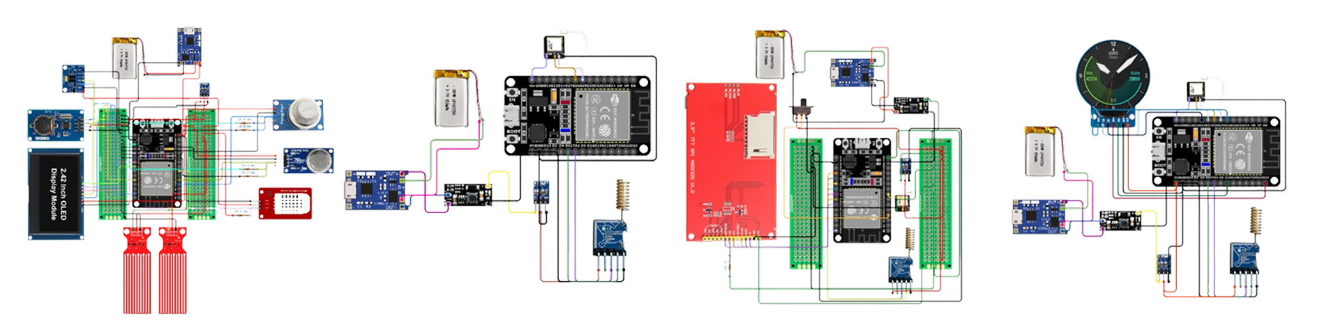
The Fritz diagram maps every connection across all three nodes — power rails, I²C buses, SPI lines, UART connections, and LoRa antenna headers. Building this before touching hardware identified every pin conflict before it became a burnt component.
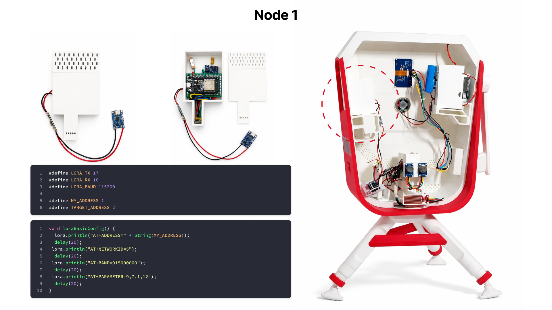
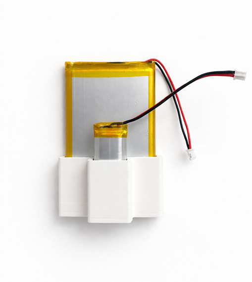
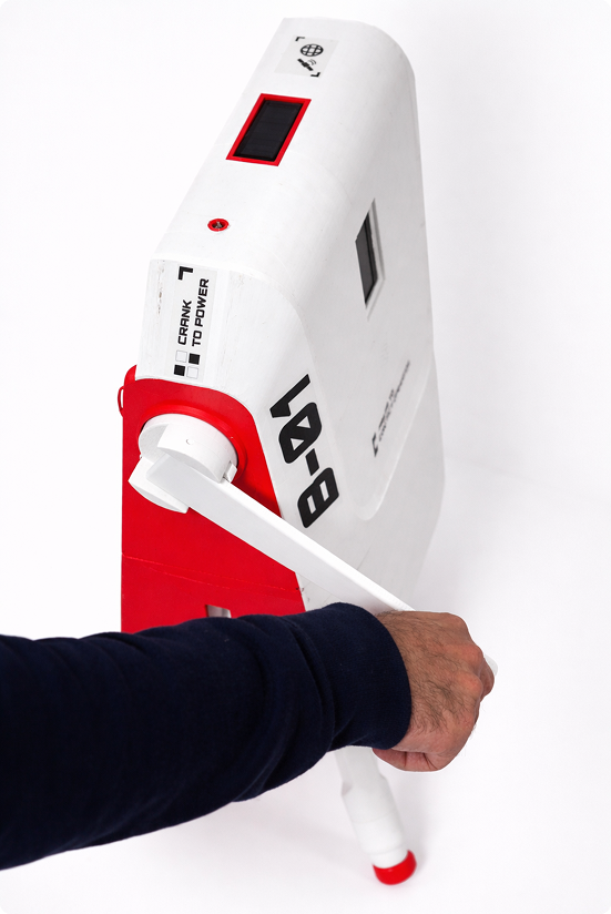
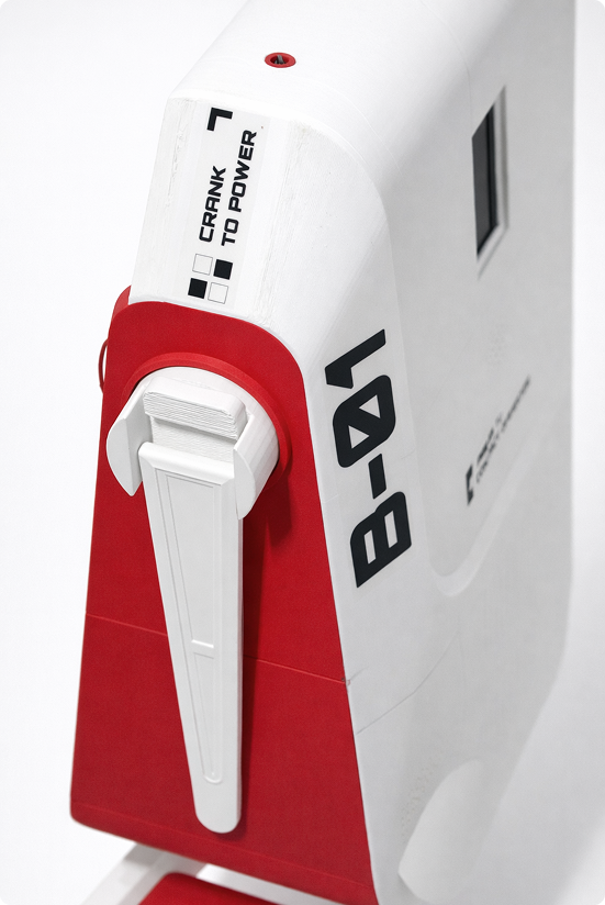
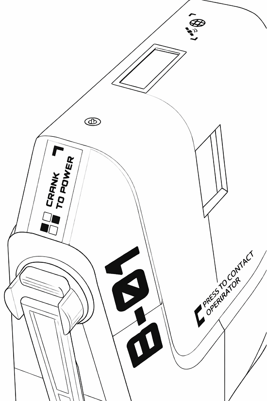
In a prolonged disaster, batteries die. The crank mechanism gives Node 1 an indefinite power source — no grid required. 60 seconds of hand-cranking generates enough charge to broadcast for 10 minutes across the mesh.
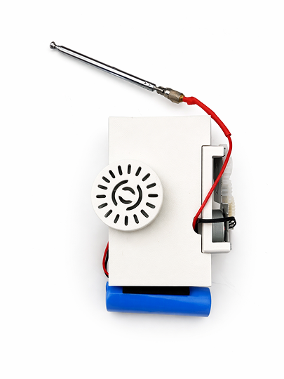
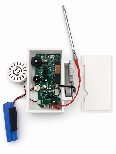
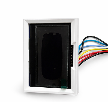
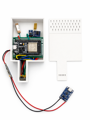
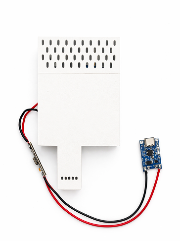
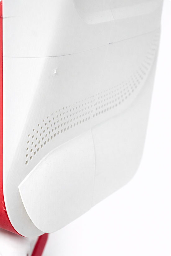
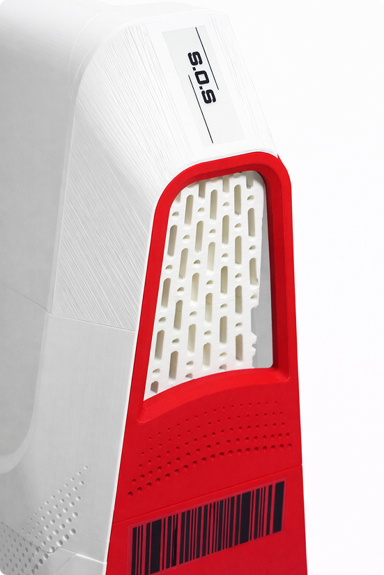
The beacon's environmental sensors sit in a vented housing — airflow without water ingress. The open-circuit view shows how tightly every module is packed; every millimetre of internal volume is accounted for.
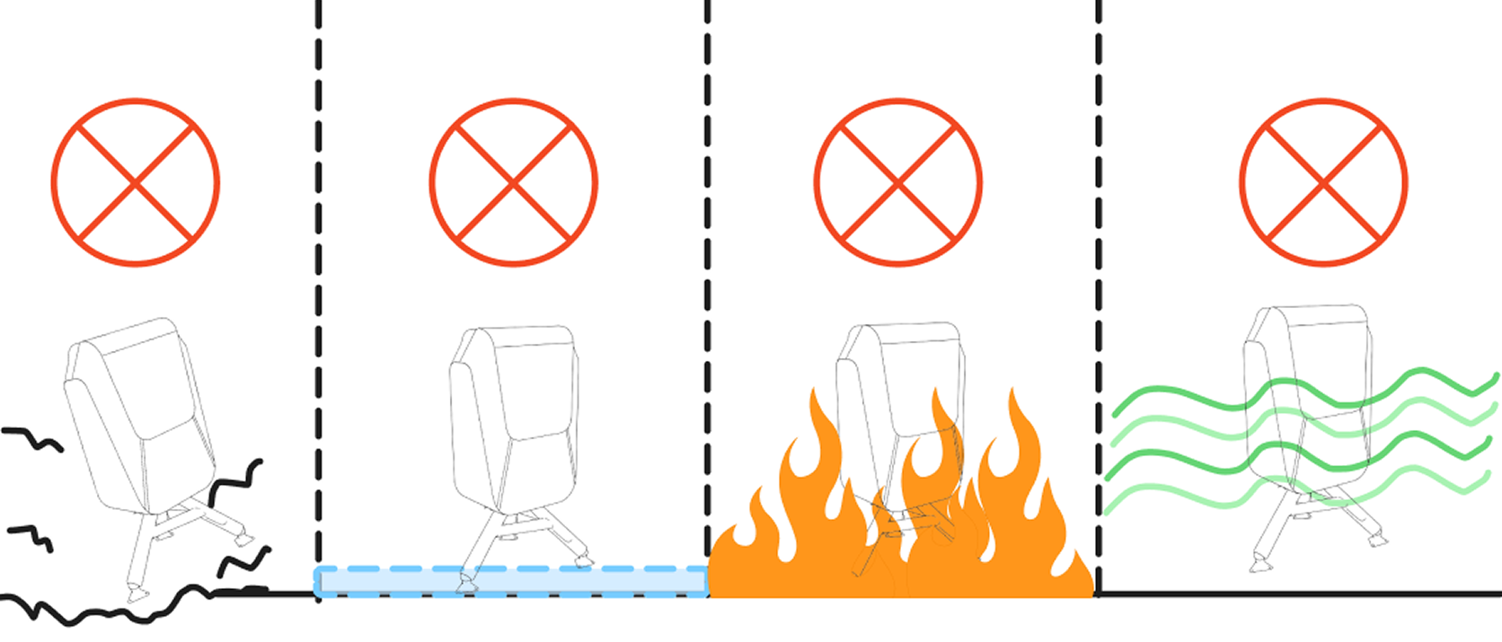
We mapped every failure mode — water ingress, signal loss, power failure, sensor malfunction — and built fallback behaviours for each. The system degrades gracefully; no single failure goes dark without warning.
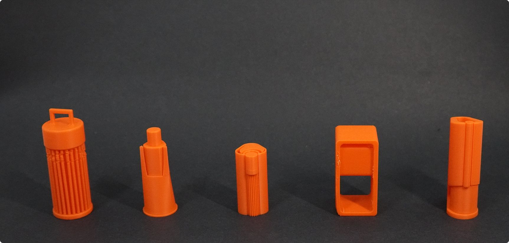
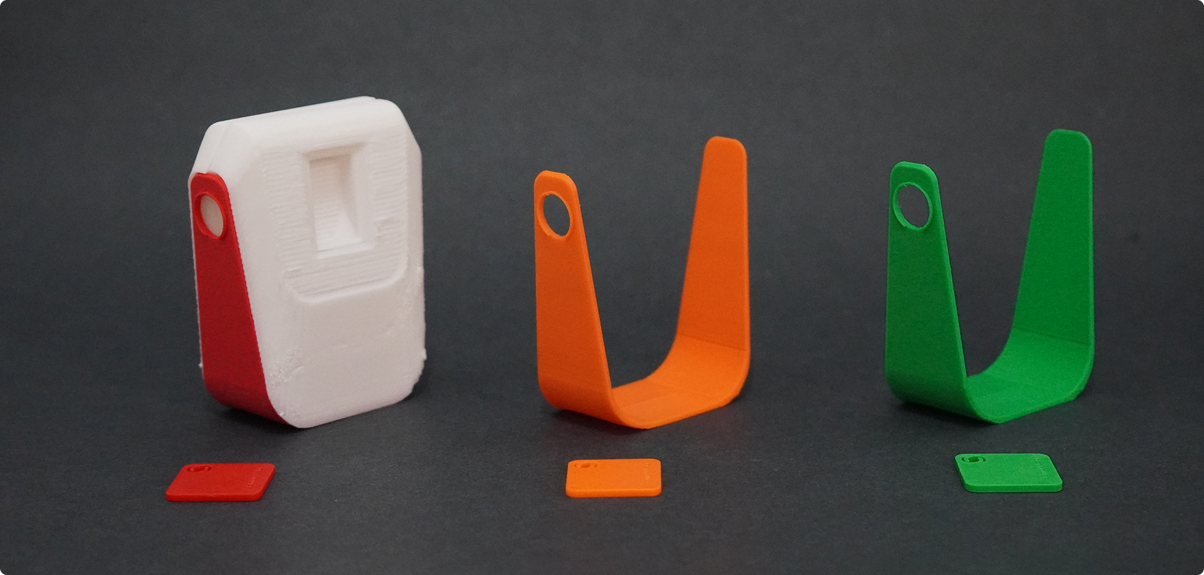
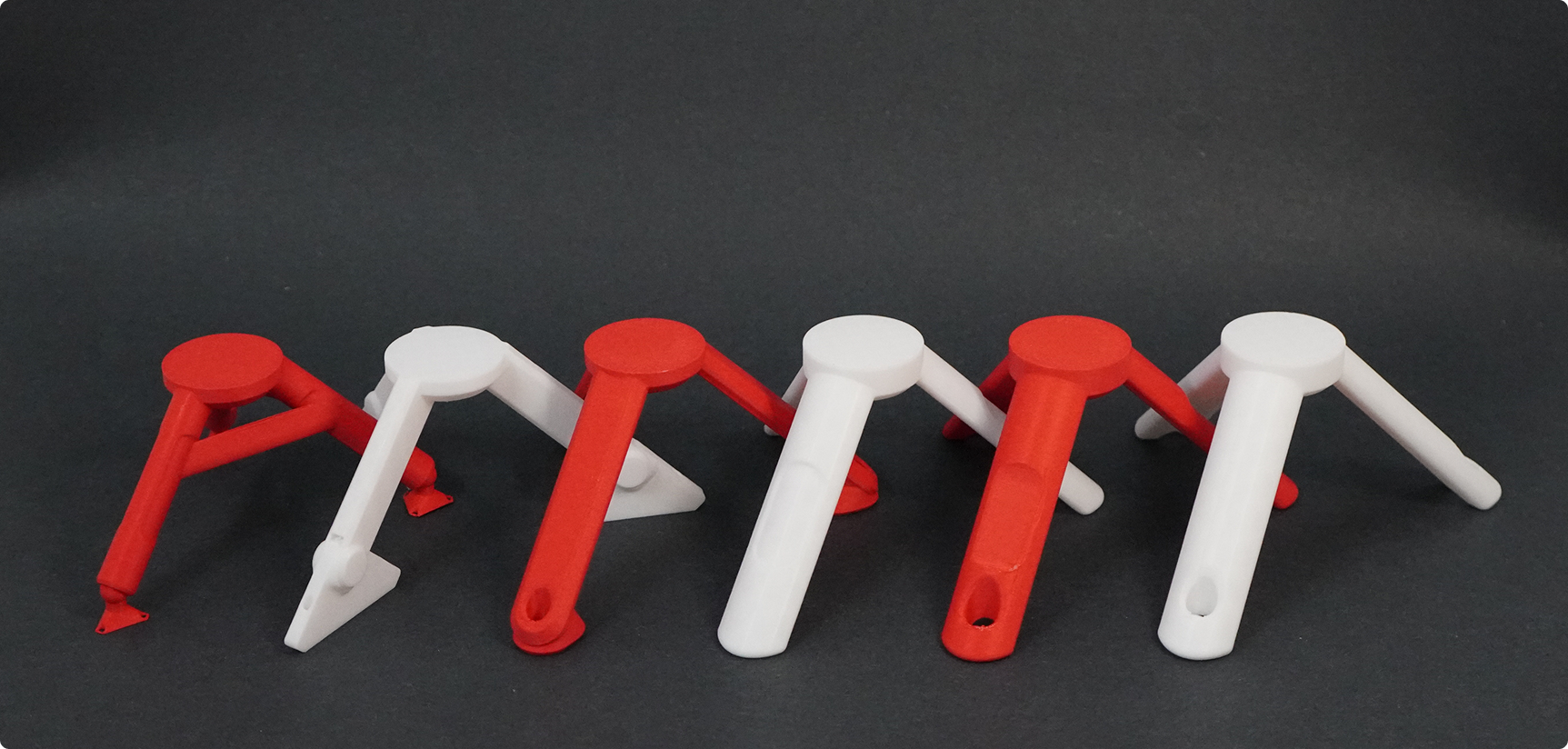
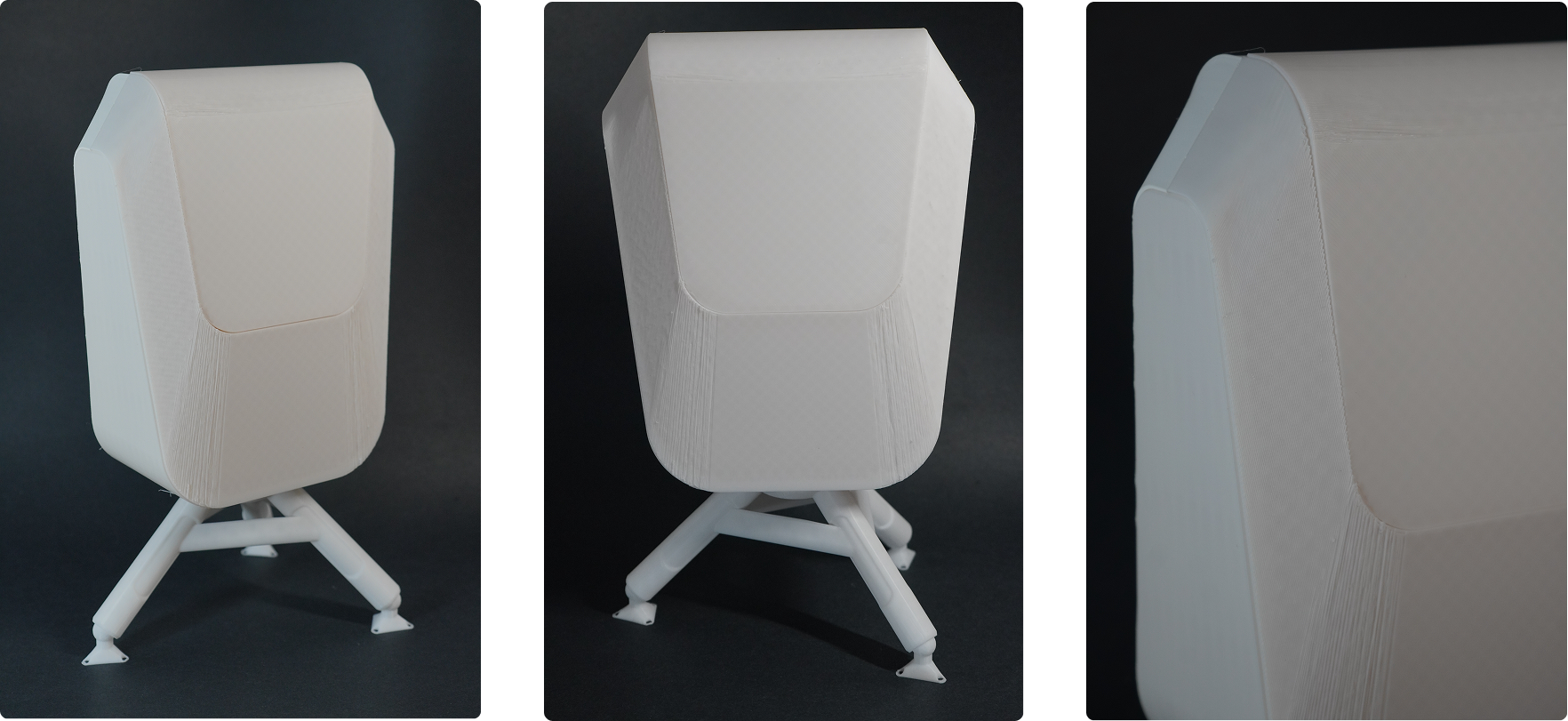
SAR orange was confirmed across colour testing — high-visibility in most natural environments while maintaining visual cohesion between all three nodes. Scale modelling validated ergonomics before any final prototyping began.
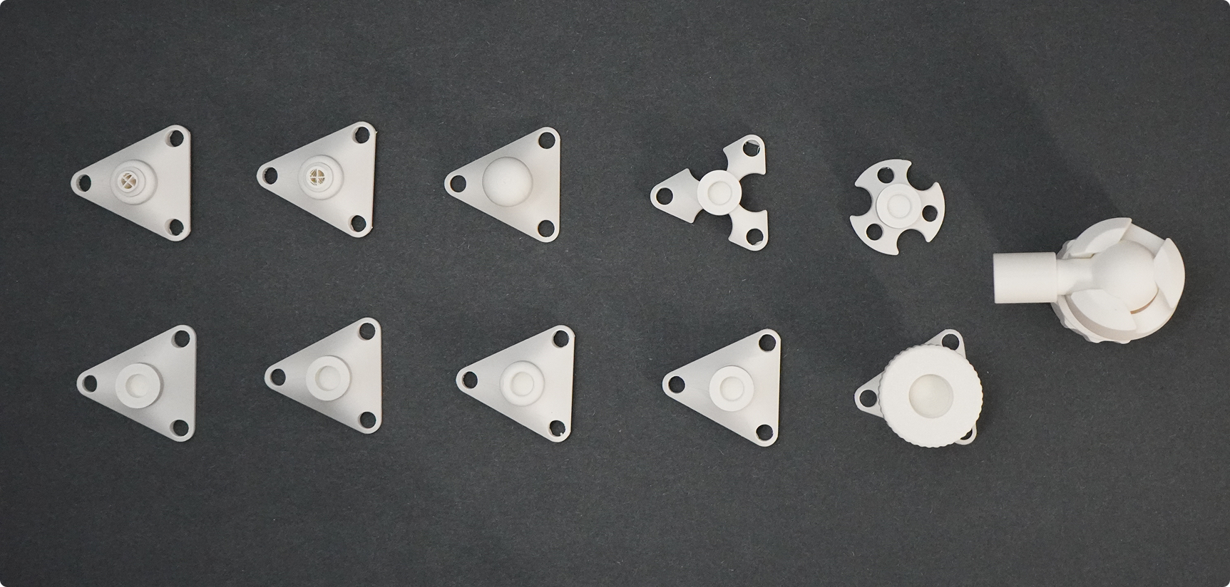
Every failure is recorded — not to showcase mistakes, but to prove iteration. Physical electronics development is a process of informed failure; each burnt component and misread datasheet sharpened the final design.
The final
system.
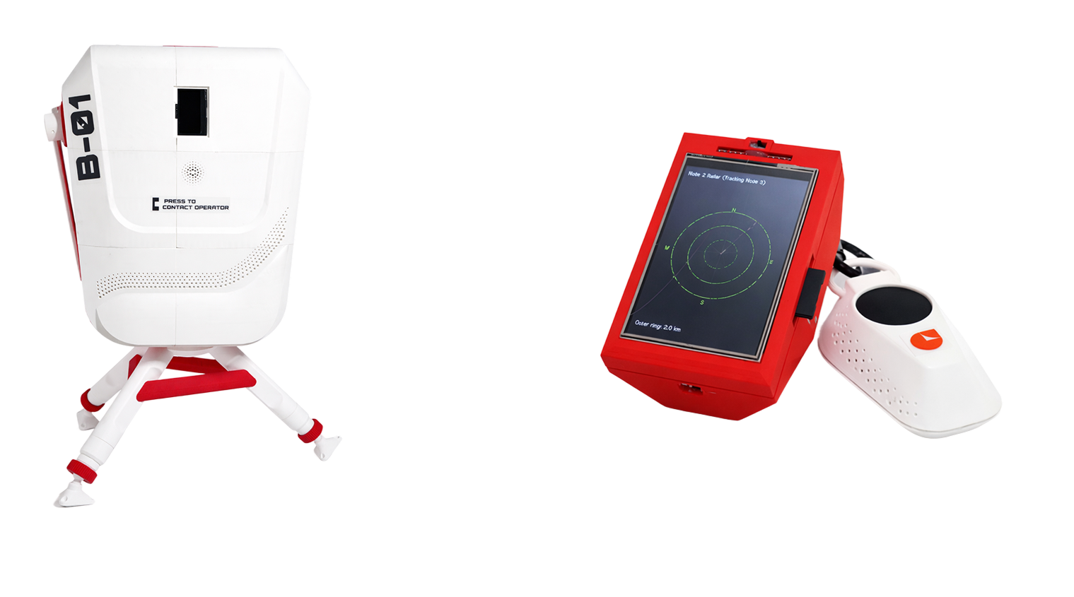
Three nodes. One mesh. Node 3 (Survivor Handheld), Node 2 (Rescue Radar), Node 1 (Base Beacon) — concluding with the exploded view of internal assembly.
One button. GPS locked. Broadcasting.
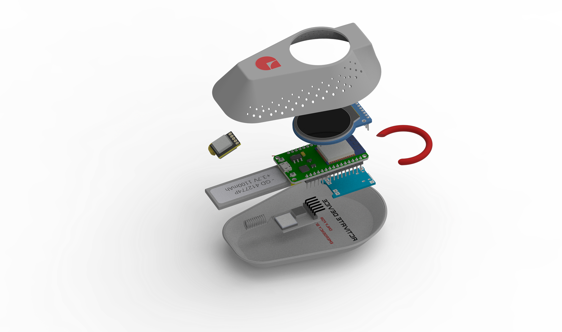
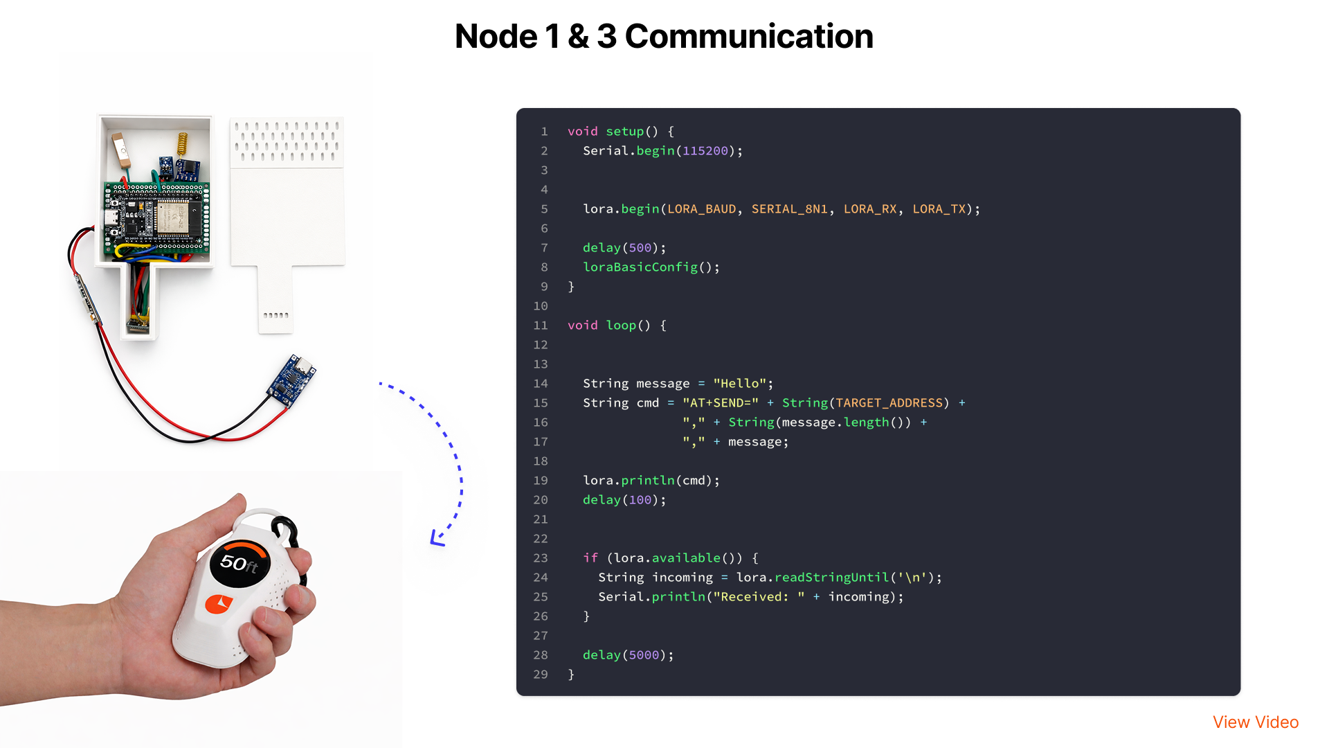
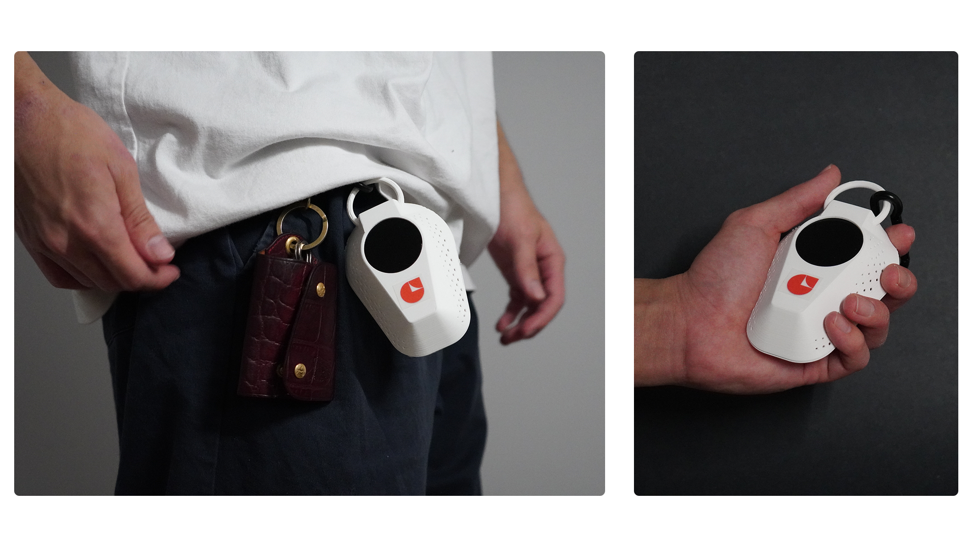
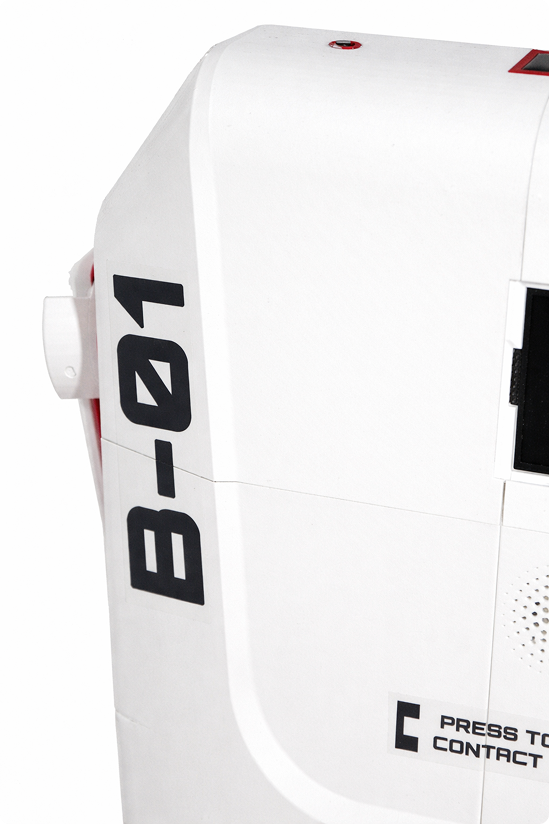
Node 3 is what survivors carry. The wearable clip attaches to a belt, bag strap, or keychain — always accessible, never in the way. A single button press activates the SOS: GPS acquires position and the RYLR998 begins broadcasting continuously over the LoRa mesh.
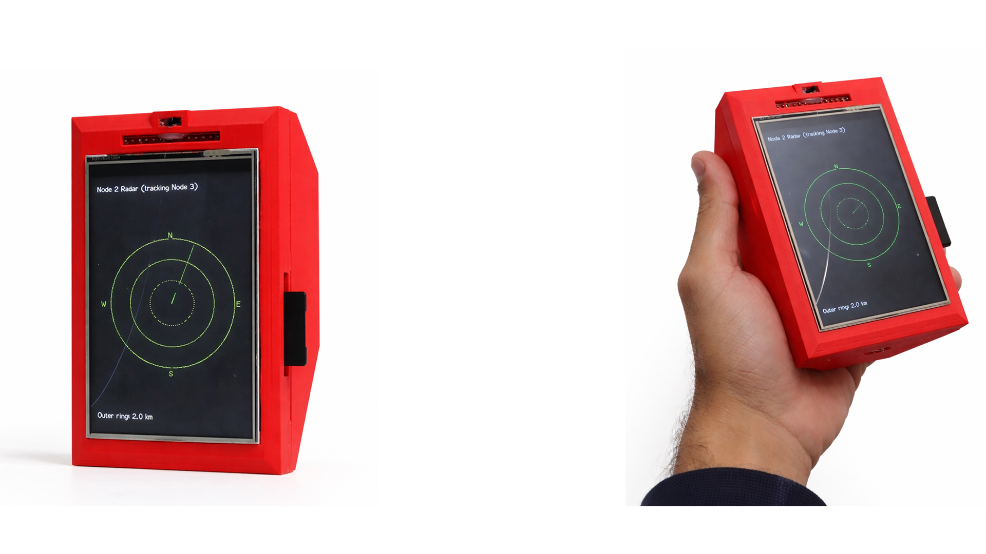
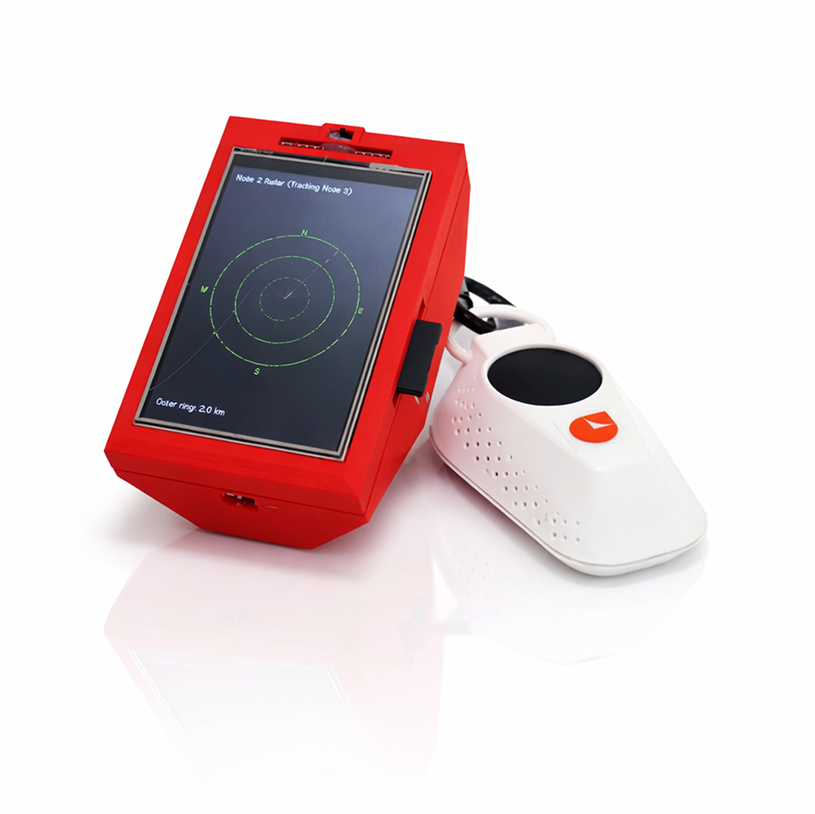
Deploy. Read the radar. Navigate.
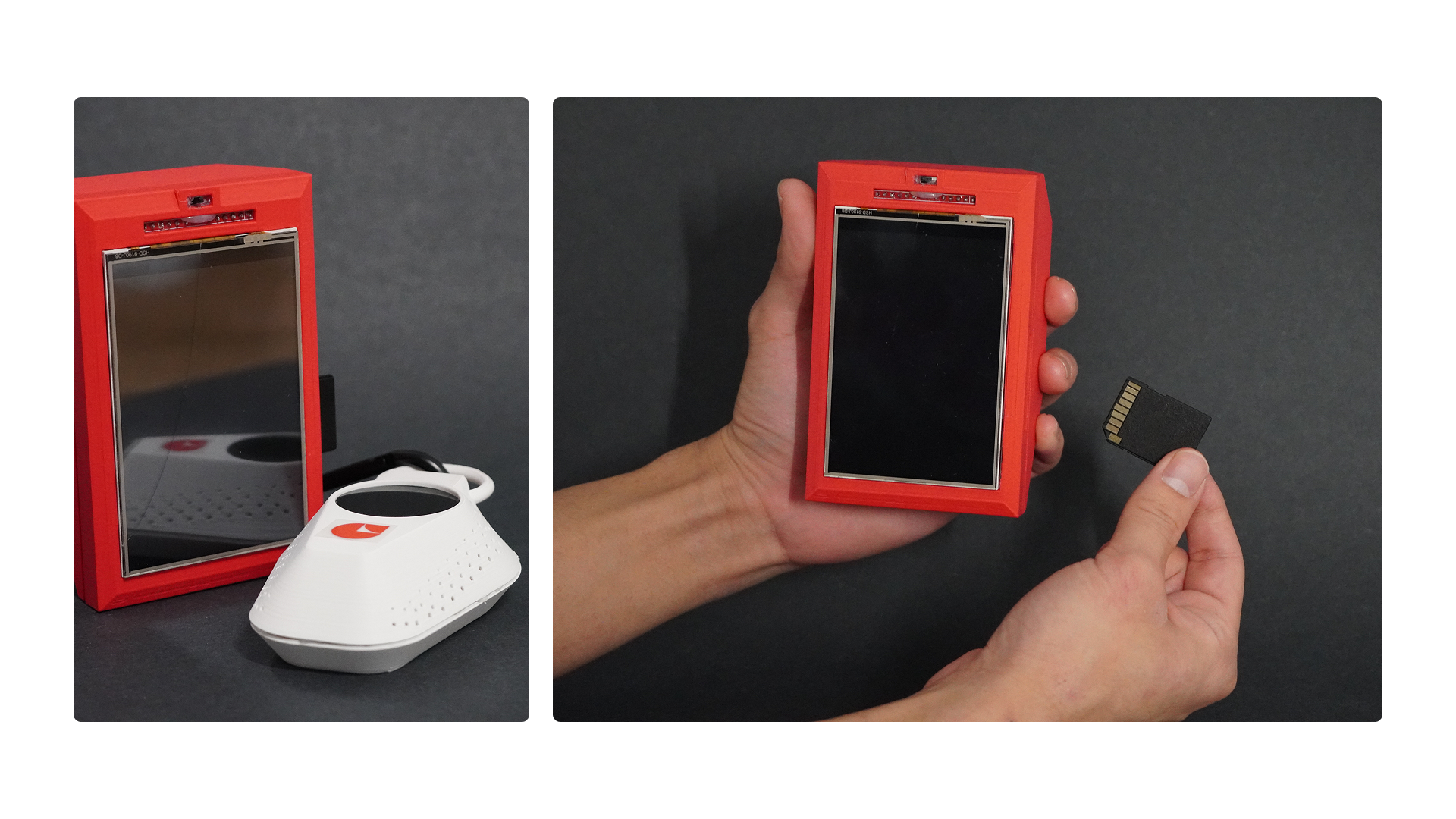
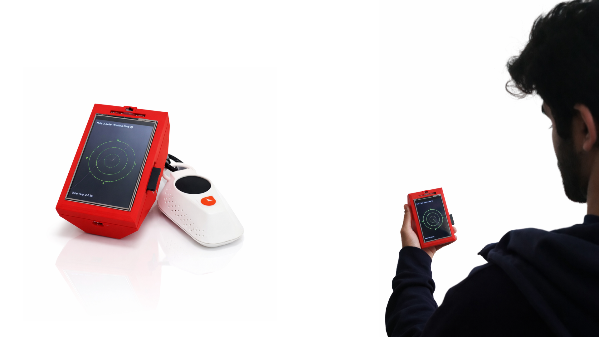
Node 2 is the field worker's tool. The radar UI displays all incoming survivor coordinates as live markers — updated every 5 seconds via the LoRa mesh. Every coordinate and timestamp is written to the SD card automatically, building a complete mission log.
Set it up. Leave it running. Command from it.
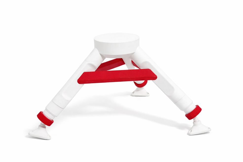
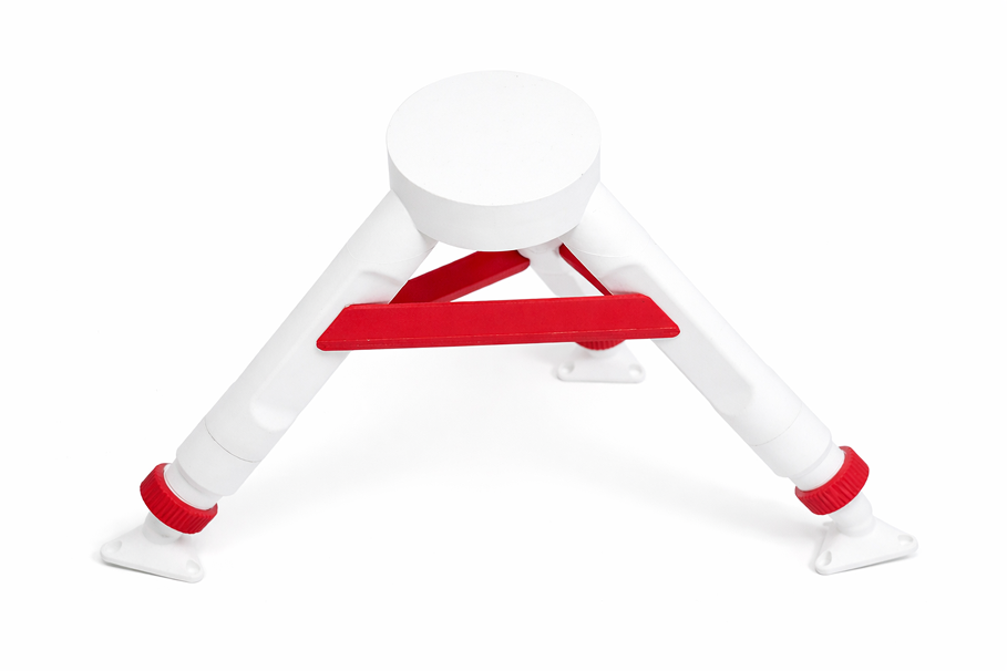
Node 1 is the persistent command centre. Tripod-mounted at base camp, it aggregates the entire mesh. The integrated crank mechanism means it runs indefinitely without mains power. Environmental sensors feed situational awareness data back to operators.
Node 2 and Node 3 share the same visual language — SAR orange, matte housing, single-point activation. A survivor's device and a rescuer's device are immediately recognisable as part of the same system.
The exploded view reveals every layer of the Node 3 handheld housing — outer shell, PCB tray, battery bay, and the single-button SOS interface. Each layer is designed to be accessed tool-free.